
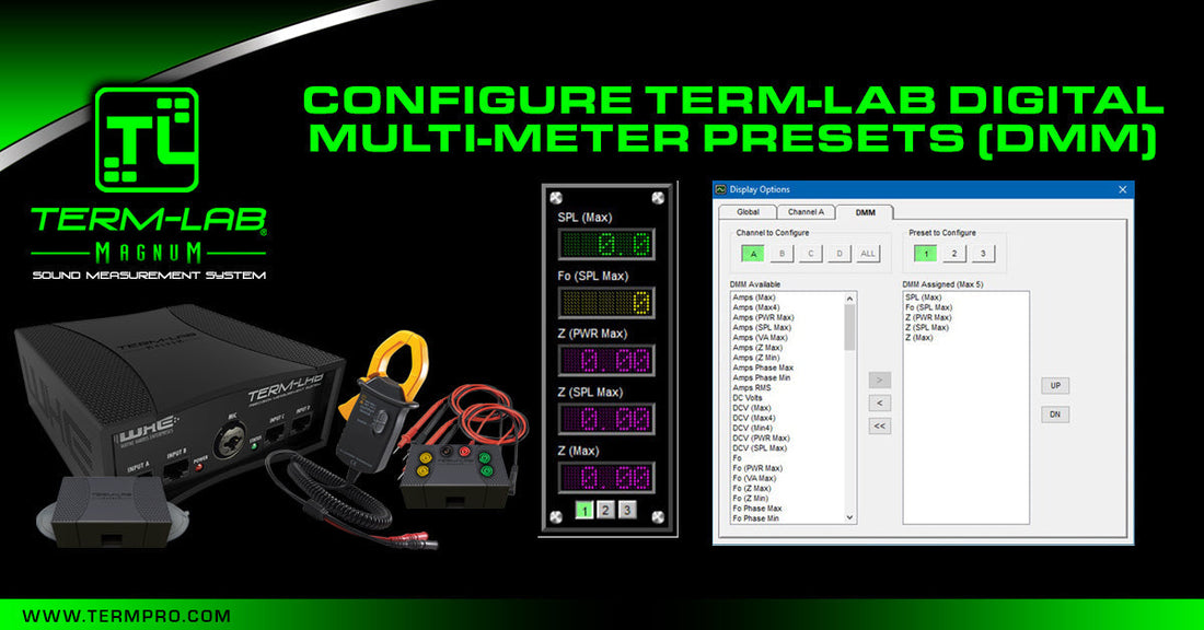
How to Configure Term-LAB Digital Multi-Meter Presets (DMM): A Step-by-Step Guide
The Term-LAB DMMs are small digital readouts that are used to display the results of various measurements or calculations that are made by the Term-LAB sound measurement system. Term-LAB incorporates 4 measurement channels. Each channel supports 3 DMM presets and each preset can be configured to display as many as 5 DMM readouts. Each DMM readout can be configured to display the results from more than 100 different measurements or calculations.
Please watch the video tutorial and then review the step-by-step instructions to learn how to configure the Term-LAB DMM readouts.
Video Tutorial
Step-by-Step Instructions
1. Open the DMM Configuration Window
The fastest way to open the DMM configuration window is by simply clicking on any of the DMM readouts. Alternatively, you can open this window by selecting "Tools / Display Settings" from the Term-LAB pull-down menu and then clicking on the "DMM" tab.
|
|
The fastest way to open the DMM configuration window is to simply click on any of the DMM readouts. In this picture, 5 DMM readouts are enabled for preset 1. |

DMM Configuration Window

The DMM configuration window is used to configure the DMM readouts
2. Select the Channel to Configure
The Term-LAB system incorporates 4 independent measurement channels named "A", "B", "C",and "D". By default, the DMM readout configuration for each channel is synchronized to that of channel A. (A future tutorial on advanced display configuration will provide step-by-step instructions on how to configure each channel independently.) In this example channel A will be configured and the remaining channels will duplicate these settings.

The channel configuration toolbar is used to select the desired channel to configure.
3. Select the Preset to Configure
Term-LAB features 3 preset buttons for each measurement channel. These presets, which are located directly below the DMM readouts on the main screen, provide an easy way to switch between user-defined DMM configurations. Each preset is configured independently.

The preset configuration toolbar is used to select the desired preset to configure.
4. Assign or Remove Measurement or Calculation
There are currently more than 100 different measurements or calculations that can be assigned to each DMM readout. The arrow buttons are used to move selections between the DMM available and DMM assigned list boxes.

The arrow buttons are used to configure the DMM readouts.
DMM Available and DMM Assigned Selection Lists
|
DMM available displays a list of measurements or calculations that are available for assignment to the selected preset. (please refer to the Digital Multi-Meter function list for a description of the measured or calculated values associated with this list.) |
DMM assigned displays a list of the currently assigned measurements or calculations for the selected preset. |


Note: A maximum of 5 DMM readouts can be displayed for each preset. The actual number is determined by the DMM configuration and available screen real estate. For example, if 5 DMM readouts are assigned but there is only enough screen resolution to show 3, then only the top 3 DMM readouts will be visible.
4a. Assign Measurement or Calculation
To assign a selection to the DMM assigned list you must first select the desired measurement or calculation from the DMM available list and then click the right arrow button. This will add the selection to the bottom of the DMM assigned list and the DMM display on the screen will be updated to show the change.
4b. Remove Assignment
To remove a selection from the DMM assigned list you must first select the item from the DMM assigned list and then click on the left arrow button.
4c. Remove All Assignments
To remove all selections from the DMM assigned list simply click on the double-arrow button.
5. Arrange the DMM Readouts
The DMM readout order can be easily arranged. Simply click on the measurement or calculation you wish to move in the assigned list and then click on the "UP" or "DN" button to shift the selected DMM readout up or down as desired.

The UP and DN buttons can be used to re-arrange the vertical placement of the DMM readouts.
6. Save Changes
When you close the DMM configuration window Term-LAB will ask you if you want to save your changes. if you select "Yes", the changes will be saved as the new default configuration. If you select "No", the changes will only be used until you close the program.

The save configuration dialog box allows you to save or discard changes.
Summary
In this training module, instructions related to the configuration of the Term-LAB Digital Multi-Meter readouts were provided. These instructions covered opening the DMM configuration window, configuring the DMM readouts to display various measurement and calculation information, re-arranging the DMM readouts on the screen, and saving these settings for future use.
For additonal Term-LAB training information, please visit Term-LAB support.
Digital Multi-Meter function list
The Term-LAB measurement system currently measures or calculates more than 100 different types of information. The following list briefly describes the items that are found in the DMM selection list.
Important Notes
The following measurement groups require the optional Term-LAB Power Probe
- amps
- dcv
- pf
- phase
- power
- va
- volts
Definitions
- max4 – the Power Probe calculates and updates power related measurements 4 times per second. These updates are called “frames.” typically, there are 4 frames per SPL measurement calculation. The "max4" value is the maximum value that was observed during the frame.
- min4 - the minimum value that was observed during a frame.
- max - the maximum value of the selected calculation
- pWR max - the value of the calculation when maximum power occurred.
- SPL max - the value of the calculation when maximum SPL occurred.
- va max - the value of the calculation when maximum va occurred.
- z max - the value of the calculation when maximum z occurred.
- z min - the value of the calculation when minimum z occurred.
- phase max - the value of the calculation when maximum phase occurred.
- phase min - the value of the calculation when minimum phase occurred.
Power Probe Current Measurements
The Term-LAB Power Probe provides the system with the ability to measure the AC speaker current provided by the amplifier. The measured values are in AC amps rms.
- amps (max) - the maximum speaker current since the start of the measurement.
- amps (max4) - real-time maximum speaker current per frame.
- amps (pWR max) - the speaker current at the time maximum power occurred.
- amps (SPL max) - the speaker current at the time maximum SPL occurred.
- amps (va max) - the speaker current at the time maximum va occurred.
- amps (z max) - the speaker current at the time maximum impedance occurred.
- amps (z min) - the speaker current at the time minimum impedance occurred.
- amps phase max - the speaker current at the time of maximum phase difference.
- amps phase min - the speaker current at the time of minimum phase difference.
- amps rms - real-time speaker current in AC amps rms.
Power Probe DC Voltage Measurements in DC Volts
The newest version of the Term-LAB Power Probe provides the ability to measure the DC voltage of the electrical system. Typically, this measurement is taken at the power input terminals of the amplifier. this feature is still undergoing development and DC voltage measurements May not be possible with some amplifier brands.
- dc volts - real-time battery voltage (maximum of the 4 power frames per SPL update).
- dcv (max) - the maximum DC voltage since the start of the measurement.
- dcv (max4) - real-time maximum battery voltage per power measurement frame (4 times per second).
- dcv (min4) - real-time minimum battery voltage per power measurement frame (4 times per second).
- dcv (pWR max) - the DC voltage at the time maximum power occurred.
- dcv (SPL max) - the DC voltage at the time maximum SPL occurred.
Frequency in Hz
Term-LAB identifies the frequency with the largest magnitude for every SPL calculation. The measured values are in Hz.
- fo - real-time frequency in Hz (largest magnitude).
- fo (pWR max) - the frequency at the time maximum power occurred.
- fo (SPL max) - the frequency at the time maximum SPL occurred.
- fo (va max) - the frequency at the time maximum va occurred.
- fo (z max) - the frequency at the time maximum impedance occurred.
- fo (z min) - the frequency at the time minimum impedance occurred.
- fo phase max - the frequency at the time of maximum phase difference.
- fo phase min - the frequency at the time of minimum phase difference.
Power Factor
- pf - real-time calculated power factor.
- pf (max) - the maximum power factor since the start of the measurement.
- pf (min) - the minimum power factor since the start of the measurement.
- pf (pWR max) - the power factor at the time maximum power occurred.
- pf (SPL max) - the power factor at the time maximum SPL occurred.
- pf (va max) - the power factor at the time maximum va occurred.
- pf (z max) - the power factor at the time maximum impedance occurred.
- pf (z min) - the power factor at the time minimum impedance occurred.
- pf phase max - the power factor at the time of maximum phase difference.
- pf phase min - the power factor at the time of minimum phase difference.
Phase Calculations
The Term-LAB Power Probe provides the system with the ability to measure the phase difference between the speaker voltage and the speaker current. These calculations are in degrees.
- phase - real-time phase difference (maximum of the 4 power frames per SPL update).
- phase (max) - the maximum phase since the start of the measurement.
- phase (max4) - maximum real-time phase per power measurement frame (4 times per second).
- phase (min) - the minimum phase since the start of the measurement.
- phase (pWR max) - the phase at the time maximum power occurred.
- phase (SPL max) - the phase at the time maximum SPL occurred.
- phase (va max) - the phase at the time maximum va occurred.
- phase (z max) - the phase at the time maximum impedance occurred.
- phase (z min) - the phase at the time minimum impedance occurred.
Power Calculations in Watts
The Term-LAB Power Probe provides the system with the ability to measure the true power that the amplifier is delivering to the speaker. True power takes the phase and waveform shape into account. The measured values are in watts rms.
- power (max) - the maximum power since the start of the measurement.
- power (max4) - maximum real-time power per frame (4 times per second).
- power (SPL max) - the power at the time maximum SPL occurred.
- power (true) - real-time true power (maximum of the 4 power frames per SPL update).
- power (va max) - the power at the time maximum va occurred.
- power (z max) - the power at the time maximum impedance occurred.
- power (z min) - the power at the time minimum impedance occurred.
- power phase max - the power at the time of maximum phase difference.
- power phase min - the power at the time of minimum phase difference.
Power Probe Diagnostics
These readings are primarily for factory use.
- probe a drops – counter showing the number of current related packets that were dropped.
- probe a offset – DC offset as detected on the Power Probe clamp inputs.
- probe low a – low current detection counter.
- probe low p – low power detection counter.
- probe low v – low voltage detection counter.
- probe v drops – counter showing the number of voltage related packets that were dropped.
- probe v offset – DC offset as detected on the Power Probe speaker inputs.
Sensor Diagnostics
These readings are primarily for factory use.
- sensor drops – counter showing the number of SPL packets that were dropped.
- sensor offset – DC offset of the SPL sensor.
SPL Measurements
the Term-LAB SPL sensor provides the system with precise sound pressure level capabilities. These measurements are in db SPL.
- SPL - real-time sound pressure level
- SPL (avg) - average SPL
- SPL (max) - the maximum SPL value since the start of the measurement.
- SPL (pWR max) - the SPL value at the time maximum power occurred.
- SPL (va max) - the SPL value at the time maximum va occurred.
- SPL (z max) - the SPL value at the time of maximum impedance.
- SPL (z min) - the SPL value at the time of minimum impedance.
- SPL phase max - the SPL value at the time of maximum phase difference.
- SPL phase min - the SPL value at the time of minimum phase difference.
System and Violation Counters
the following information is used to show violation status.
- tl samples - counter showing the number of completed measurements taken.
- tl red light - counter showing the number of red light violations in Bass Race.
- tl overshot - counter showing the number of overshot violations in Bass Race or Top Dog.
- tl high freq - counter showing the number of high frequency violations during a measurement.
- tl high power - counter showing the number of high power violations during a measurement.
- tl high voltage - counter showing the number of high DC voltage violations during a measurement.
- tl high z - counter showing the number of high impedance violations during a measurement.
- tl performance - under development
- tl frame match - under development
VA Calculations
The Term-LAB Power Probe enables the system to calculate va. va is the product of AC voltage and AC current. VA calculations do not incorporate any phase information. Therefore, VA power measurements will almost always be higher than true power measurements.
- va - real-time va
- va (max) - the maximum va since the start of the measurement.
- va (max4) - real-time va per frame (4 times per second).
- va (pWR max) - the va at the time maximum va occurred.
- va (SPL max) - the va at the time maximum SPL occurred.
- va (z max) - the va at the time maximum impedance occurred.
- va (z min) - the va at the time minimum impedance occurred.
- va phase max - the va at the time of maximum phase difference.
- va phase min - the va at the time of minimum phase difference.
Power Probe Speaker Voltage Measurements
The Term-LAB Power Probe provides the system with the ability to measure the AC voltage provided by the amplifier to the speaker. The measured values are in AC volts rms.
- volts (max) - the maximum speaker voltage since the start of the measurement.
- volts (max4) - maximum real-time speaker voltage per power measurement frame (4 times per second).
- volts (pWR max) - the speaker voltage at the time maximum power occurred.
- volts (SPL max) - the speaker voltage at the time maximum SPL occurred.
- volts (va max) - the speaker voltage at the time maximum va occurred.
- volts (z max) - the speaker voltage at the time maximum impedance occurred.
- volts (z min) - the speaker voltage at the time minimum impedance occurred.
- volts phase max - the speaker voltage at the time of maximum phase difference.
- volts phase min - the speaker voltage at the time of minimum phase difference.
- volts rms - real-time speaker voltage in AC volts rms.
Power Probe Impedance Calculations in Ohms
The Term-LAB Power Probe enables the system to calculate the speaker load impedance based on the measured voltage and current. The measured values are in ohms.
- z – real-time calculated load impedance.
- z (max) - the maximum load impedance since the start of the measurement.
- z (max4) - maximum real-time load impedance per power measurement frame (4 times per second).
- z (min) – the lowest load impedance since the start of the measurement.
- z (min4) - minimum real-time load impedance per power measurement frame (4 times per second).
- z (pWR max) - the load impedance at the time maximum power occurred.
- z (SPL max) - the load impedance at the time maximum SPL occurred.
- z (va max) - the load impedance at the time maximum va occurred.
- z phase max - the load impedance at the time of maximum phase difference.
- z phase min - the load impedance at the time of minimum phase difference.
- z (va 0 deg) – the real-time calculated load impedance based on va.